Sampling of the Rayleigh scattering along a length of optical fiber allows the realization of a distributed sensor system where every point along the fiber acts as a sensor. This method allows quasi-continuous measurement of temperature and strain profiles over distances of up to 70 m. The spatial resolution is in the order of millimeters, which provides the equivalent of thousands of conventional individual sensors.
Fiber-optic sensor technology
Since many years, fiber sensors have been used for temperature sensing or the measurement of mechanical quantities, in particular in environments where electrical sensors reach their limits. This can be in environments with large electromagnetic fields or difficult chemical conditions. Similarly, it may be for applications in which great distances need to be covered or in which the compact diameter and low weight of the glass fiber is advantageous.
Fiber based systems are made up of a monitoring unit which is connected to the passive sensor fiber. The monitoring unit transmits light from a tunable frequency laser or a broadband source into the fiber. Characteristics of the light traveling within the fiber are modified as a function of the temperature and the strain. These changes are detected in the back-scattered light collected by the monitoring unit analyzed and converted into strain and temperature data.
On the sensor side a distinction is made between single point sampling and distributed sampling. Single point sensors can be realized by writing fiber bragg gratings into the fiber which then generate a reflection centered on a wavelength depending on the strain and temperature of the fiber. Alternatively in a second version, the temperature dependent absorption properties of a semiconductor crystal attached to the tip of the fiber is read out to provide an optical end-point sensor.
As these sensors only work at discrete measurement locations, both the number of sensors as well as their precise position are a critical feature in the design of the overall system, in particular with regard to the total cost. With this type of sensors it is a fundamental challenge to capture events if their location is not previously known, such as the development of temperature hotspots or crack formation within a concrete structure. In such cases, individual sensors positioned incorrectly can lead to completely flawed measurements and interpretations.
A similar problem occurs if temperature and strain profiles have a steep gradient, or if spatially extended structures (2- or 3-dimensional) need to be precisely monitored. Thus, local events can remain undetected due to an insufficient number of sensors.
Systems which allow a quasi-continuous distributed measurement along the sensing fiber provide significant advantages. These systems use light back-scattered from the fiber material itself, which provides the required temperature and strain related information.
Two measurement methods have been established for long distance applications, making use of the Raman and Brillouin scattering within the fibers. These systems allow distributed temperature and strain measurements over distances in the range of tens of kilometers. However, the distance resolution of Raman and Brillouin based distributed sensing systems is limited to approx. 1 m. The limiting factor is the extremely low intensity of the scattered light used here, which makes it very difficult to increase the resolution.
Viewed in absolute terms, the Rayleigh scattering in the back-scattered light is also small, but significantly larger than the Raman and Brillouin scattering. In recent years the US company Luna Technologies has succeeded in developing a system which uses the Rayleigh scattering to making distributed measurements with resolutions in the millimeter range.
Optical frequency domain reflectometry (OFDR)
An essential part of a sensor system making distributed measurements is a reflectometer providing spatial resolution. In many cases, Raman and Brillouin systems work with an optical time domain reflectometer, (OTDR), in which the monitoring unit transmits a short light pulse and uses the time of flight of the back-scattered light to determine the location of the reflection.
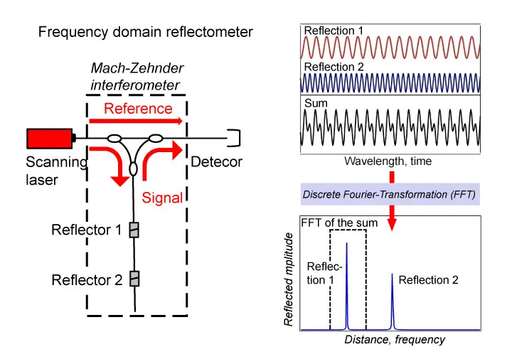
For the Rayleigh sensor technology, a significantly higher resolution is required than that which can be attained with an OTDR. This is attained using a coherent optical frequency domain reflectometer, c-OFDR (Figure 1).
In c-OFDR systems, the beam of a variable frequency CW laser is coupled into a fiber-optic Mach-Zehnder interferometer. One fiber represents the reference arm with a fixed path length, whilst the second arm is formed by the sensing fiber. The light scattered back from the sensing fiber interferes with the light from the reference arm at the output coupler. Varying the frequency of the laser wavelength creates a periodic signal at the detector, the frequency of which depends on the location of the respective segment of the fiber scattering the light back. The further the segment is away from the detector, the greater the frequency of the interference signal. As the detector receives the backscatter signals from all the segments simultaneously, the total signal must be split into its frequency components using a Fourier transform technique. The frequencies then correspond to the signal locations in the fiber. The amplitude of each frequency component indicates the strength of the respective reflection.
The attainable spatial resolutions depend on the wavelength range over which the laser can be tuned. Commercial systems from Luna Technologies work at 1550 nm and can be tuned over a maximum range of 90 nm. This corresponds to a spatial resolution of 10 µm. With fiber lengths of up to max. 70 m, the system provides the Rayleigh backscatter signal of 7 million fiber segments per laser scan.
Analysis of the Rayleigh signal
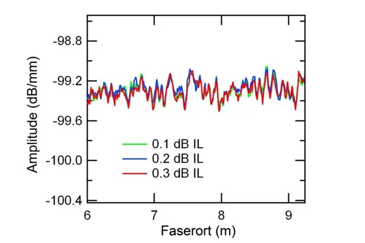
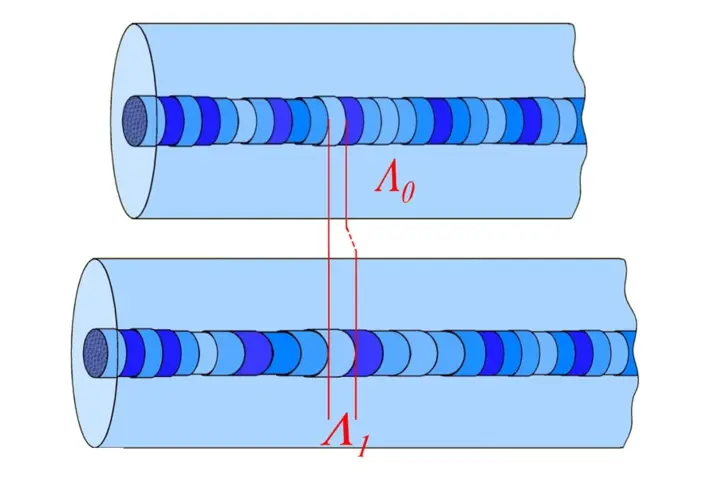
When a commercially available glass fiber is scanned using OFDR, a fluctuating intensity profile of the Rayleigh scattering along the glass fiber will be detected. This profile is absolutely stable when the measurement is repeated under unaltered external conditions, such that it represents a characteristic "fingerprint" for a specific fiber segment (Figure 2). The reason for this lies in the nature of the Rayleigh scattering. It is caused by the elastic scattering process at local defects, refractive index variations or distortions of the waveguide geometry which although it varies from segment to segment, is still stable.
If you now change the temperature or strain conditions within the fiber, the fingerprint is spatially stretched or compressed (Figure 3). This phenomenon is the basis for the Rayleigh sensor technology as the changes to the local Rayleigh pattern can be converted into local temperature or strain measurements.
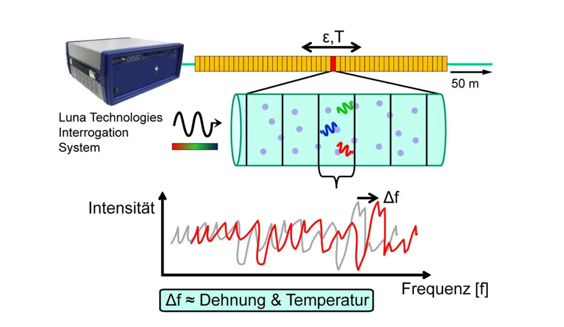
In order to achieve this, the measurement signal returned from the fiber is divided into small analysis windows corresponding to ≥ 1 mm sections, and the signal this contains is transformed into the frequency range (Figure 4). The result is a fluctuating reflection pattern depending on the frequency. Changes to the temperature or strain condition of the fibers lead to a frequency shift Δf, which is proportional to the changes in the external conditions affecting the fiber. This process basicallyresembles measurements based on fiber Bragg gratings, where similarly, the shift in reflected frequency peaks is detected, when the external conditions change.
Finally, to provide a distributed measurement, the analysis window must be slid over the fiber length by a software algorithm so that a complete profile along the path is created.
Properties of Rayleigh sensor technology
The combination of OFDR and Rayleigh scattering thus represents a system making distributed measurements of temperature and strain with special properties:
High spatial resolution: The variable analysis window determines the spatial resolution. With the current commercial systems it can be set to a minimum of 1 mm and the total fiber length can be up to 70 m. However, this does not represent a physical boundary but is a limited by the data processing.
Flexible, virtual sensor positions: In principle, a single laser scan always provides all the relevant information. However, the analysis window can be positioned in any position with a variable width, both continuously as well as at fixed measurement locations. Thus, the complicated question of physical sensor positioning no longer arises as this is now determined in the software either before or after the measurement.
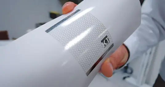
Standard glass fiber as a sensor: As even glass fibers with low scattering still produce enough Rayleigh scattering, it is not only possible to use many commercial standard fibers, but also special types after appropriate calibration. However the coating of the fiber must be adapted for the respective application. For temperature measurements of up to 350°C, the fiber needs a polyimide coating, and up to 700°C, a gold coating is required. For strain measurements, the coating needs to optimally transfer the strain changes on the object to the fiber. The maximum strain that can practically be reached with a standard glass fiber is approx. 30 000 µm/m.
High measurement sensitivity: Temperature changes can be captured with 0.1°C resolution, changes in strain with 1 µm/m resolution.
Parallel interrogation of all sensors: With the measurement method described, all segments of the fiber are read simultaneously. The maximum rate is up to 5 Hz. This allows easy observation of the overall dynamics of an object measured with the system.
Applications
The range of possible applications for distributed Rayleigh sensor technology is extensive. This method is particularly useful when a large number of temperature or strain sensors need to be interrogated with a high density.
There are applications in practically all areas of research and technology. Two examples are described in the following which illustrate the special features and also the robustness of the method.
Testing and monitoring concrete structures
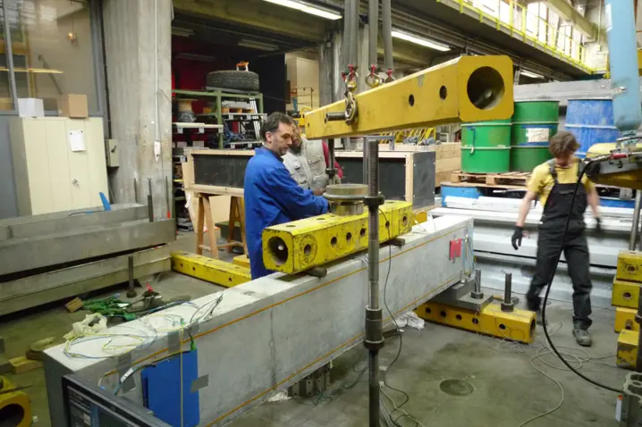
A research project was carried out by Electricité de France EDF to investigate the load bearing capacity of different structural elements in which a fiber-optic cable was integrated into a reinforced concrete beam alongside a conventional strain gauge (Figure 5 and Figure 6). The subsequent load test was taken to the non-elastic regionwhich lead to localized cracks appearing in the structure.
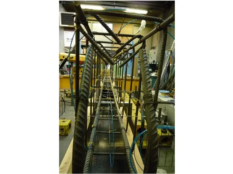
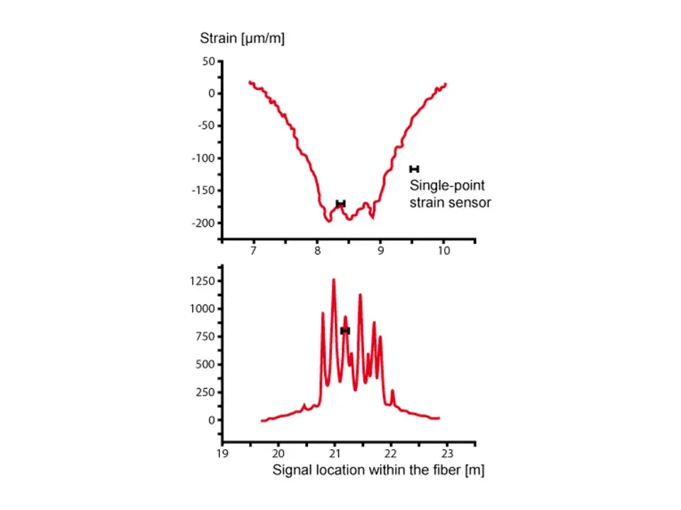
Figure 7 shows the strain changes recorded over the full length of the beam. The upper graph shows the segment under compressive stress, the lower graph under tensile stress. The distinct peaks allow localized, considerably higher strain values to be identified which correlate precisely with the formation of cracks observed in this segment.
Although the conventional sensor captures one of these cracks, it is purely by accident. The other cracks which appeared in adjacent locations are not identified at all. This is where the superiority of the distributed measurement technology can be seen as it registers all events and significantly simplifies the interpretation.
Distributed measurement of high temperatures
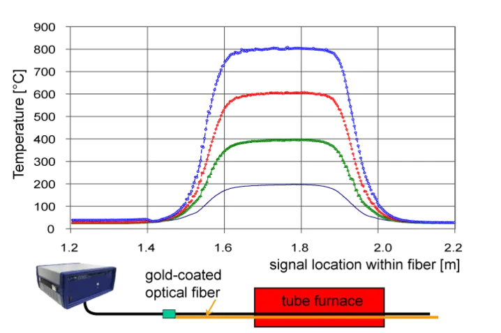
Rayleigh sensor technology is ideally suited for recording complete temperature profiles, particularly in high temperature ranges, as can be found for example in the exhaust system on cars, in microwave ovens or large furnaces in the steel industry.
Figure 8 shows several temperature profiles which have been captured with the aid of a gold coated fiber in a tube furnace. Such commercially available fibers can be permanently operated at up to 700°C, and for short periods at even higher temperatures.
Outlook
Rayleigh sensing is a glass fiber based process for making a distributed measurement of temperature and strain which features a particularly high level of spatial resolution in the millimeter range. Due to the internal design, comprising reliable components from the optical telecommunications industry, this technique has so far proven to be a very robust and flexible solution for everyday applications.
To extend the measurement options, development is currently focusing on the subjects "Range" and "Processing speed". In the near future, a version of the device is being planned which extends the measurement range from 70 m to 2 km with a spatial resolution in the centimeter range. This makes it possible to monitor extended objects. Furthermore, it allowsmeasurement configurations in which the measurement location is further remote from the monitoring unit.
For dynamic investigations the market requires acquisition rates in the range of up to 1 kHz. Here the combination of OFDR technology and continuously written fiber Bragg gratings is a promising approach.