A portion of the bridges in Germany has become quite old and is not designed for the constantly increasing loads caused by today’s traffic volume. Currently, those responsible face the task of finding an economically sensible solution for managing such existing structures so that they can be used as long as possible while remaining safe.
Fiber optic-based monitoring methods offer good prerequisites for this. At the University of Stuttgart, in cooperation with Schömig-Plan Ingenieurgesellschaft, the application of continuous strain-measuring fibers as permanent monitoring for crack detection and monitoring was investigated in laboratory and field tests, installed under practical conditions on a highway bridge, and its performance tested with positive results.
Recent advancements in high-resolution continuous fiber optic sensors (Distributed Fibre Optic Sensing, DFOS) based on Rayleigh scattering, when properly installed, offer the possibility to monitor critical structural areas almost comprehensively. A DFOS consists of an optical fiber and a reading unit (interrogator) with a laser light source. The sensor is a single-mode (SM) glass fiber, similar to those used in telecommunications for long-distance transmissions. This enables continuous detection and localization of strain distributions by measuring Rayleigh scattering with a lateral resolution of about 1 mm over a sensor length of up to 50 m.
Principle of Rayleigh Sensing
In Rayleigh sensing, laser light is coupled into the glass fiber and the Rayleigh light backscattered by the fiber material is scanned with high resolution using an optical measurement method. The result is a characteristic pattern along the fiber, called the fingerprint, which is different for each section but extremely stable and reproducible. This is due to the amorphous structure of glass, which is statistically distributed along the fiber. When external strain changes occur, this fingerprint is clearly shifted apart or compressed, so that the change in the local Rayleigh pattern can be converted into strain.
Since every point of the fiber is sensitive to this effect, the entire fiber along its full length acts as a distributed sensor. By coupling up to eight sensors, a measurement length of 400 m at a measurement rate of 2.5 Hz is currently achievable. These fiber optic measurement systems are also insensitive to electromagnetic interference or other electrical disturbances.
From Laboratory Test to Field Trial
DFOS are currently mainly used for monitoring bored piles or tunnel linings. They have not yet become established for permanent monitoring of bridges. However, this could change in the future: At the University of Stuttgart, in close cooperation with Schömig-Plan Ingenieurgesellschaft, the behavior of strain-measuring cables applied post-installation on a surface was first examined in laboratory tests.
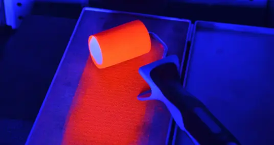
The focus was on finding a compromise between the robustness of the application method to protect the fiber, the meaningfulness of the measurement results, and the feasibility of installation on the structure. The application variants and measurement technology investigated were then tested in a four-week field trial on a highway bridge under real environmental conditions and traffic loads (Figure 1).

The quality of the local strain measurement of the fiber attached to the concrete surface largely depends on the strain transfer: from the carrier material to the adhesive, from the adhesive to the outer coating, through the intermediate layers of the coating, and from the inner coating to the sensing fiber itself. At the same time, the coating of the sensing fiber must also provide the necessary protection and therefore be sufficiently robust. Commercially available fibers, for example, come with acrylic and polyamide coatings, or in more durable versions, with PE or steel sheathing.
A certain reduction in strain is actually desirable to protect the fiber from breaking. Such a reduction of strain in the fiber core can also be achieved by choosing adhesives with low Shore hardness, such as permanently elastic potting compounds. To determine the actual local strain, calibration of the strain measurement cable results in combination with the application method is necessary. This ensures that the results are traceable in accordance with the applicable DIN/ISO standards.
Installation on a prestressed concrete highway bridge
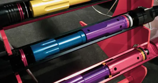
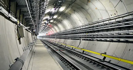
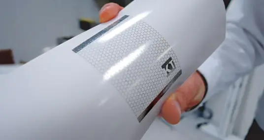
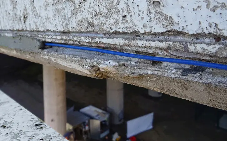
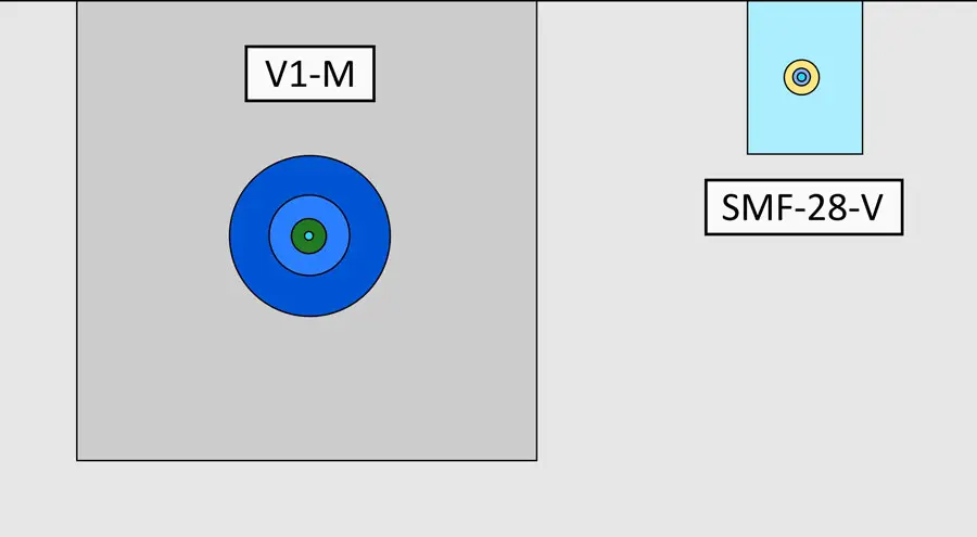
Based on the laboratory tests, strain measurement cables with an ethylene-propylene coating (V1) and an SM fiber with a Hytrel-acrylate coating (SMF-28) were chosen as sensors for the field trial. To protect them during the four-week test on the prestressed concrete highway bridge from environmental influences, vandalism, and detachment due to insufficient bonding, they were laid in grooves in the concrete cover (see Image 2 and Image 3). This eliminated the need for elaborate surface preparation on the structure and additional securing of the cables during the curing time of the adhesive.
Since the expansion joints of the selected highway bridge were already being monitored, an area with existing cracks and known crack movement was identified in advance for testing the applicability of the strain measurement cables. In total, four cables, each about 25 meters long, were installed in loops across the expansion joint for crack monitoring.
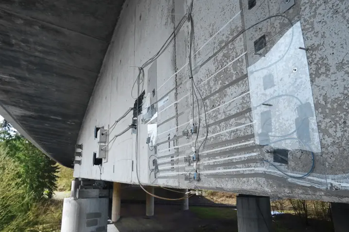
To check the influences from traffic and general strain behavior, the strain measurement cables are also laid straight along the edge of the girder to the middle of the span. The unbonded part of the cables is additionally mounted and secured on the superstructure to test the data volume and functionality of the sensors over large lengths up to 50 m.
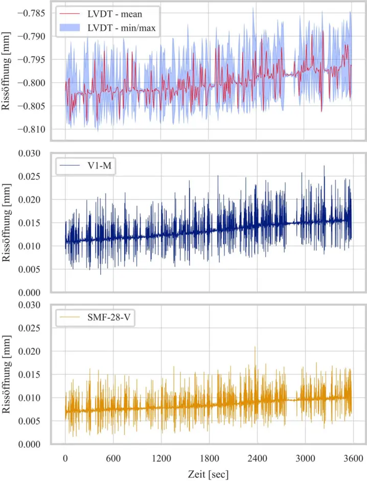
For verification of the fiber optic strain measurements, displacement sensors are installed staggered over the height of the expansion joint. Temperature compensation during measurement was also taken into account. The fiber optic readout system then transmits the measurement data from the strain measurement cables to a workstation. Here, they are continuously cleaned, evaluated, and stored in files. Observing the real-time measurements, one can see, for example, in the field area with straight cable installation, a rising and falling of the measurement curve every time a heavy vehicle crosses the bridge (Image 5).
More Quality in Structural Monitoring
The field test produced positive results. It demonstrated that continuous fiber-optic measurement technology is suitable for long-term monitoring of critical bridges. Currently, the only remaining challenge lies in managing the large volumes of data generated by continuous measurements — work on this issue is ongoing.
In addition, the automated data evaluation is to be expanded with an alert system, and the monitoring of additional existing bridges is currently being prepared. The field test also showed that this innovative monitoring method can be successfully applied in other areas of structural engineering, such as building construction or delicate shell structures. This represents a significant quality improvement for structural health monitoring.