MAN Energy Solutions Strategy:
The industries we serve account for a large part of global CO2 emissions. We realize that this provides us with enormous leverage to solve the emission problem. That’s why we get out of bed every morning.
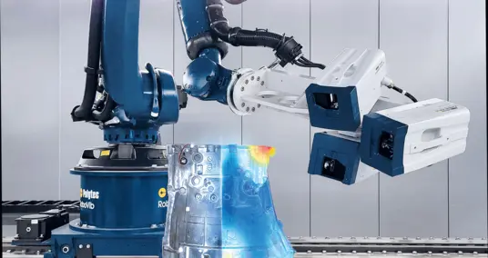
At MAN Energy Solutions, we offer a comprehensive engine portfolio, propeller, and stern equipment and turbochargers for the maritime sector. Reliability is an essential aspect of our sector and especially vital on ships. During the development phase, simulation models are validated and optimized using modal tests, and examined until the components are released for series production. We use a laser scanning vibrometer to gather data.
In practice, the quality of the measurements depends on a variety of factors. This article systematically examines the influences on measurement results. These investigations should assist practitioners working in the field of vibration measurement.
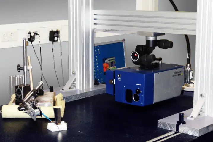
Measurement setup
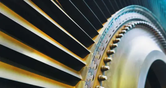
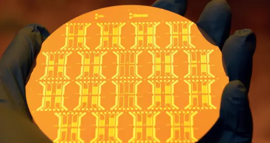
The influences are demonstrated using components from exhaust gas turbochargers, which have a low dampening and a complex geometry that both significantly increase the mode density during measurement and simulation.
Temperature influence
The impact of the component temperature on the measurement results, and therefore on the comparison with the simulation, is often underestimated. The changing Young’s moduls is the cause.
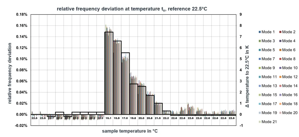
The deviations measured in Fig. 3 may already be significant for subsequent MAC alignment. The linear coherency between frequency and component temperature within the examined temperature range is also evident here. The approximate temperature influence should then be calculated and any deviations in the component temperature (or ambient temperature) should be documented during the measurement. This is particularly useful if there are a large number of measuring points or a high frequency resolution, which extend the subsequent measuring times of the sequentially operating scanning vibrometer.
Deviation in the grid position for the MAC alignment
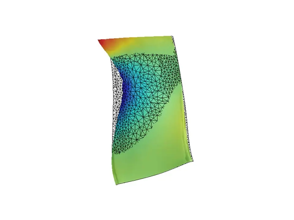
A modal test is intended to validate the simulation model. The Modal Assurance Criterion (MAC) is a proven indicator for this. By comparing the eigenmodes from the calculation and measurement, the degree of correlation for each mode can be determined. Values >0.95 must be targeted.
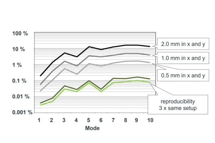
The following test setup was applied: The object under investigation was an axial turbine blade, whose geometry was loaded from the FE to the PSV software. It was then moved to the initial position in steps of 0.5, 1.0 and 2.0 mm, and the impact on the MAC values was observed. After the object was set up and evaluated in the initial position three times, the spreading of MAC values was used as a basis for the analysis. The results are displayed in Figure 4.
The values in the result deviate more as the mode increases and the eigenmodes become more complex, whereby the difference can be as much as 20%.
The accurate setup of the measurement system (3D alignment) and the object is therefore essential for a good MAC alignment. On the other hand, this means that for an object with a size of approx. 50 mm, a setup error of 0.5 mm, i.e. approx. 10% of the test specimen size, is responsible for a MAC value error of approx. 0.02–1%, regardless of the mode, and can therefore be ignored when analyzing the MAC value.
Boundary conditions: free-free
The test will only show the same natural eigenfrequencies and eigenmodes if the boundary conditions of the simulation can be reproduced in the test. The free-free boundary condition used by the simulation engineer can be attained only approximately in reality. The test comes as close as possible, but any deviations in the eigenfrequencies demonstrate how successful the test was.
Two “Free-Free” approximations were compared:
- Support in rigid foam board
- Support in rubber bands
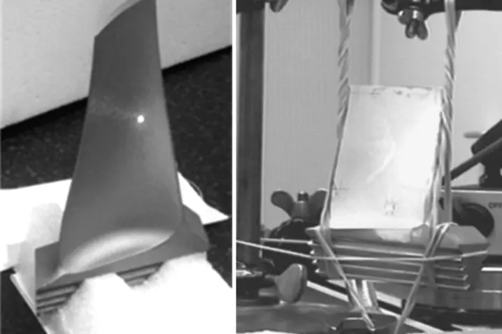
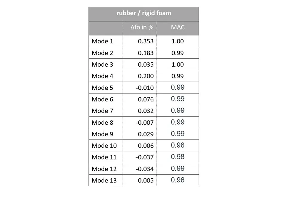
If the frequency deviations of the two support types are compared, the result is clear. In this case, the support type has no significant influence. It is more important that the support in the hard foam reliably maintains the position of the object so that a single 3D alignment can be used, even for the serial measurement of multiple test specimens.
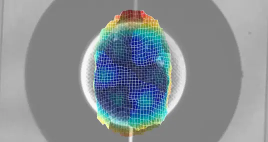
Influence of the real contour on the ideal contour (CAE data)
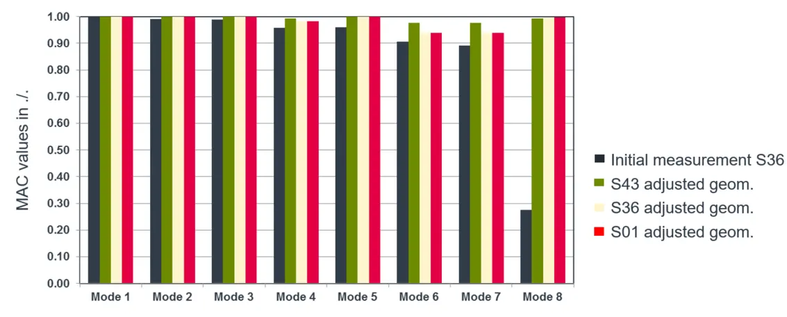
As shown in Figure 8, it was not initially possible to measure mode 8 (initial measurement S36) metrologically due to the difference between the ideal and real contour. After the test specimens were measured geometrically and used to create new FE models for the existing real contour, for the three test specimens S36, S43 and S01 the agreement for this eigenmode was within an outstanding range.
Excitation position
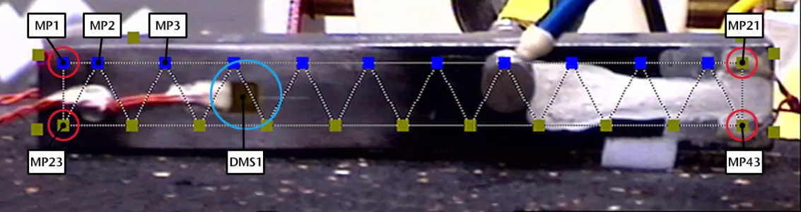
In an experiment on a bending bar, the influence of the excitation position on the transfer function is determined using strain gages and PSV. A modal hammer was used for excitation.
In order for the H1 PSV/strain gage transfer function to be evaluated as a characteristic, the vibrational velocity measured with the PSV laser vibrometer was used as a reference here, instead of the force.
As a result, Figure 10 shows that the excitation position has an influence on the vibrational velocity, depending on the excitation position along the bar, but not on the H1 transmission function of mode 1.
Summary
The influence of temperature on objects with a temperature-dependent module of elasticity is not negligible. This must be taken into special consideration when carrying out extensive tasks involving long sample times and unstable temperature conditions.
The incorrect positioning of the measurement grid on a test specimen in an order of magnitude of approx. 1% (0.5 mm @ 50 mm) results in a 0.02…1.0% change in the MAC value, depending on the mode. In other words, MAC 1 ideally changes to MAC 0.998 to 0.99, which is negligible.
Using rigid foam as a means of support for carrying out free-free calculations on turbine blades is totally permissible and allows quick and easy positioning, especially in the case of serial measurements.
If deviations of the real geometry from the ideal geometry are possible, they must be checked. If necessary, a calculation with the correct real geometry for the MAC alignment must be added.
Varying the excitation location along a bending bar did not have any influence on the eigenmode.