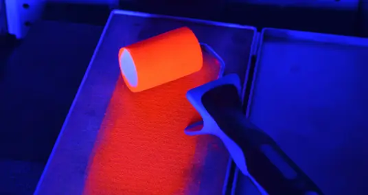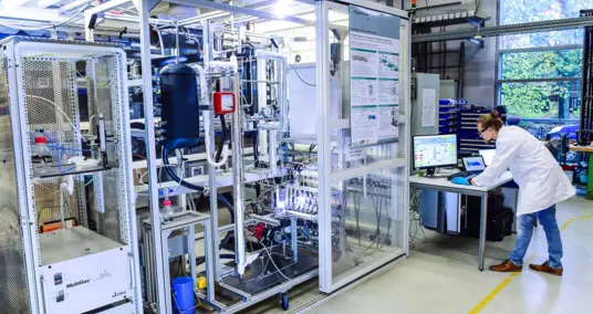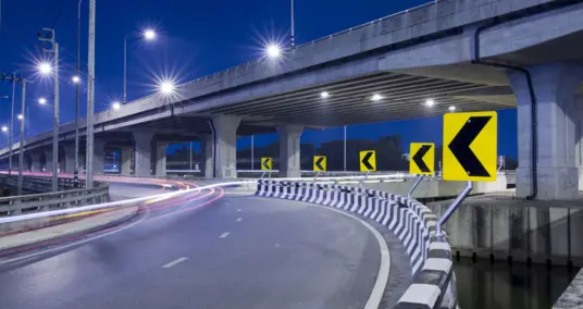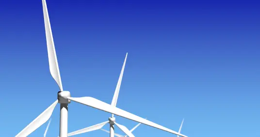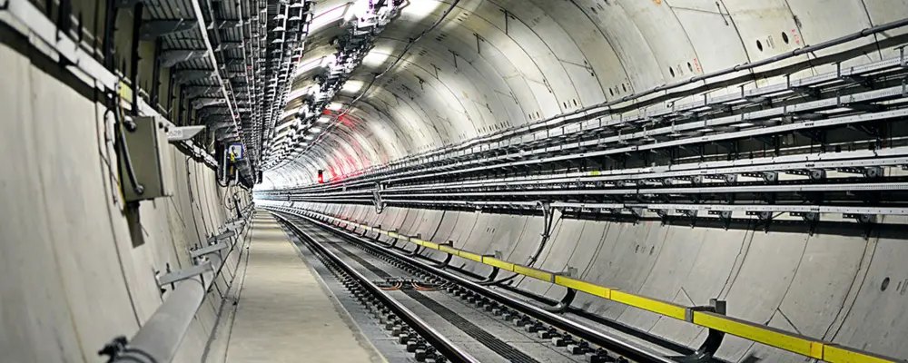
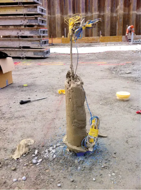
Stones, blocks, steel, cement, concrete, and mortar slurry—all combined with large, heavy, clumsy, and noisy construction machinery—don’t exactly sound like the ideal environment for a fragile glass fiber (Figures 1 and 2). Yet it is precisely there, on construction sites, that fiber-optic sensors are needed. Changes in ground load, for example due to new construction, also lead to changes in volume. This results in heaving or settlement, which can also affect surrounding structures.
The Technology
There are various established methods for monitoring construction sites, but these are generally limited to point-based information. For instance, the displacement of a measurement point can be determined geodetically, or the change in length of a section can be recorded using an extensometer. However, what happens in between remains unknown. Distributed fiber-optic sensing offers methods that allow continuous measurements over long distances. The Swiss company Marmota Engineering specializes in fiber-optic monitoring solutions for geotechnical applications and is working intensively to establish this technology on construction sites as an accepted and advantageous alternative.
For the monitoring of long, one-dimensional structures such as pipelines, distributed sensing solutions have been available for some time. These systems can record strain at every meter along a cable of up to 30 kilometers in length. With Rayleigh sensing systems from the U.S. manufacturer Luna, powerful tools are now available for applications that require much higher spatial resolution. Such systems can measure strain over a distance of 70 meters with spatial resolution in the millimeter range. This makes it possible to define thousands of “individual strain measurement segments” along a single cable—with high accuracy in the microstrain range (change in length in micrometers per meter).
Borehole sensors in landslide areas and excavation pits
When a distributed fiber-optic sensor is installed in a borehole, strain can be precisely monitored along the depth. The information obtained makes it possible to quickly detect critical settlements caused by additional loads from construction or by slope creep movements occurring at any angle relative to the borehole axis.
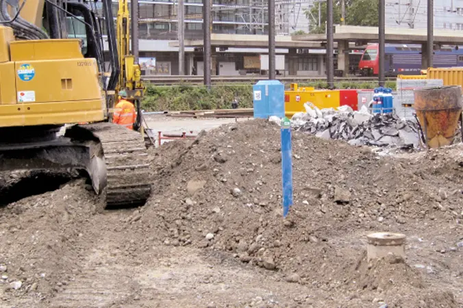
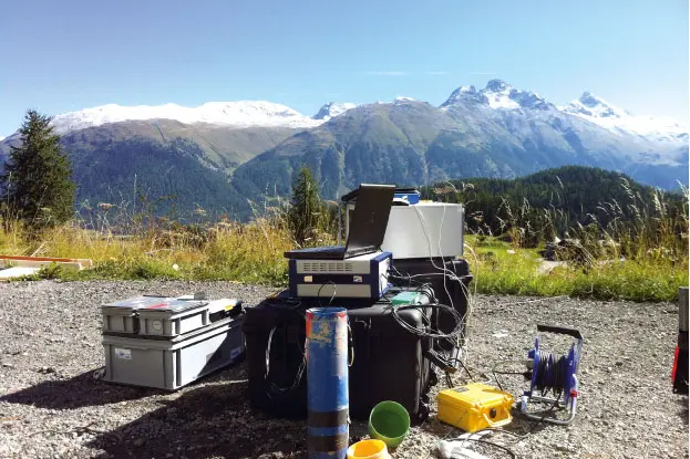
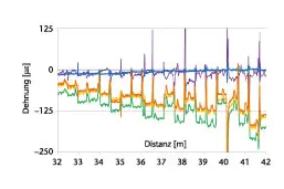
Especially in creeping slopes, the shear plane—that is, the spatial boundary of the landslide at depth—can be very thin, requiring high-resolution measurements to quickly locate it. For boreholes up to 70 meters deep, Rayleigh sensing is particularly well suited, as it can record strain at every centimeter along the borehole. Several borehole projects have been carried out and analyzed in recent years, including multiple projects in the Swiss Alps (Figure 3). These studies have shown that the Rayleigh system can detect and locate the shear plane in a short time, with lower installation and measurement effort compared to conventional inclinometers, which are based on measuring tilt within the borehole.
Infrastructure Monitoring
An example from infrastructure monitoring may illustrate the strengths of distributed sensing even more clearly. As part of the century-scale Crossrail project, in which two new railway tunnels traverse the entire city of London, a particularly vulnerable section of an existing underground tunnel was instrumented. The new tunnels in the already heavily perforated urban underground pass just a few meters from existing tunnels that are up to a hundred years old.
These tunnels are still in operation, so the existing structures had to be monitored meticulously during the excavation of the new tunnels. In addition to quantitative deformations, the type of deformation was also of great interest in this project. Specifically, it was important to determine whether the load was carried through deformations at the joints between individual cast-iron tunnel segments or through deformations of the segments themselves (Figure 6). To answer this question, four strain sensors per meter of tunnel would have been required — amounting to 280 individual sensors over 70 meters — or just a single distributed Rayleigh strain sensor.
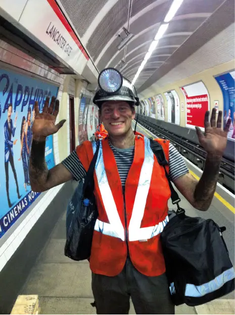
It is evident that both the installation of a single sensor cable and the subsequent measurements required far less effort than installing hundreds of individual sensors and analyzing them separately—especially considering that installation could only take place at night between 1 a.m. and 5 a.m. Even so, the instrumentation was still demanding: the heat and decades of accumulated grime tested the team to their limits (Figure 4).
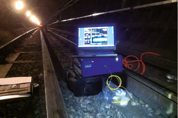
By the end of 2012, the tunnel boring machine had passed beneath the instrumented section. For two weeks, in collaboration with ETH Zurich and Imperial College London, which were operating additional instrumentation on site, the sensors were continuously monitored (Figure 5).
Conclusion and Outlook
The examples shown above, as well as other commercial applications in recent years, have demonstrated that Rayleigh measurement technology offers several advantages over conventional methods. This allows project owners and infrastructure operators to take faster and more targeted action before damage occurs. Alternatively, costs can be saved by measuring rather than overdesigning.
The current limitations of the application are primarily related to instrumentation: the choice of sensor and the attachment method must be adapted to the specific problem, and it must be ensured that the sensors remain functional throughout the entire monitoring period. This also includes accounting for the maximum strain that the sensors can withstand before the fiber breaks.
In general, the technology has already proven itself in several projects. The main focus now is to make these new measurement capabilities more appealing to a wider audience. Only when project engineers are aware of these monitoring methods can they incorporate them into their projects. This allows them to sleep more peacefully, with the assurance that all critical points are being monitored continuously—that is, without gaps.
Acknowledgements
The Crossrail project, and especially the research in this field, was carried out in collaboration with the Geotechnical Institute of ETH Zurich and Imperial College London.