The SADE project (SmArt high lift DEvices for next generation wings) of the 7th European Framework Program (Grant Agreement 213442) studied “smart” morphing mechanical elements of next generation wings, which was aimed at improving aerodynamic performance, fuel efficiency, as well as reducing noise and emissions in all stages of flight, especially landing.
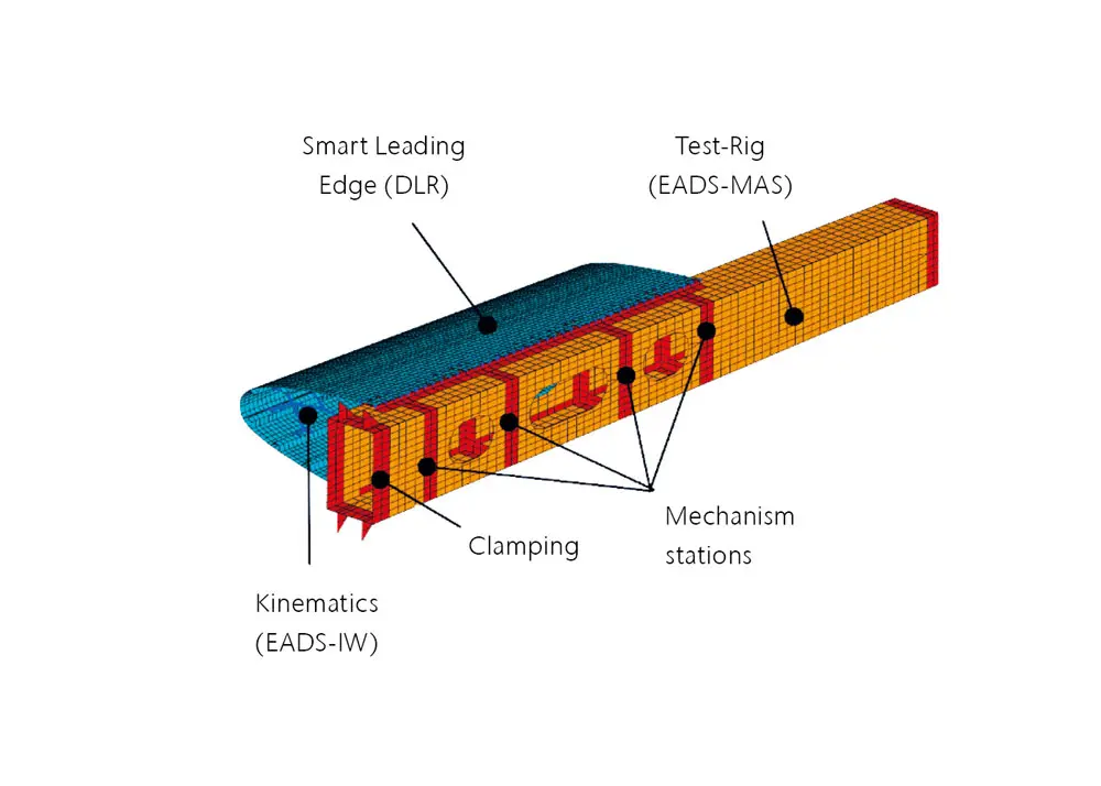
The project investigated a number of adaptive control concepts. One of the options developed by German experts from the DLR and Airbus Group (formerly EADS), is an adaptive, smart morphing slat or leading edge structure, which attaches directly to the wing box (figure 1).
An important step in studying this concept was the creation of a large-scale prototype aircraft wing section with a morphing slat, and testing it in the large, low speed “TsAGI 101” wind tunnel, (figure 2). The three-section adaptive slat includes a reinforced elastic skin made from glass-fiber-reinforced plastic.
As part of SADE’s immensely complex computational and experimental work, experts from the Central Aerohydrodynamic Institute (TsAGI), a Russian State Research Center, participated in the design and manufacture of a prototype’ measurements of aerodynamic balance in the T-101 wind tunnel, and identified the dynamic and static stiffness characteristics of a wing section. This work is relevant not only to the safety requirements of wind tunnel testing of aeroelastic phenomena (flutter, buffeting, etc.), but also to the need to validate the CAD geometry and finite element model (NASTRAN) of the prototype using experimentally determined natural frequencies and mode shapes.
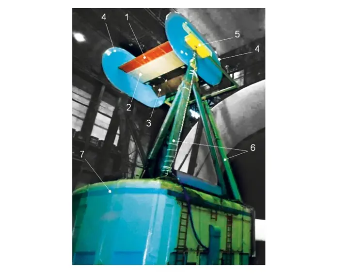
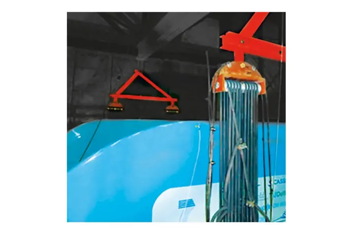
To achieve the required boundary conditions when performing experiments, the prototype was suspended on either side from two sets of elastic cords which were hung from special cross members, mounted to hooks on a bridge crane (figure 3).
The main dynamic characteristics of the prototype were determined from two different approaches:
- the standard stepped sine method for finding resonances using an electrodynamic shaker together with contact transducers for measuring vibration,
- the non-contact method of scanning laser Doppler vibrometry (LDV) with pulsed excitation of free damped oscillations using an impact hammer with integrated force transducer.
For the standard method, the structure was excited with a Prodera EX220SC electrodynamic shaker and dynamic characteristics were recorded using LMS SCADAS III / Stepped Sine LMS Test.Lab hardware and software coupled to PCB 333V32 contact sensors.
Non-contact measurements were performed with a Polytec PSV-H4 system, and vibrations of the structural elements were excited with a PCB 086E80 impact hammer hitting the metal parts or the stiffening ribs of the prototype.
In figure 4, natural modes of vibration of the prototype computed using NASTRAN (bottom row of images) are compared to data acquired experimentally using the non-contact method (top row) and the standard method (middle row).
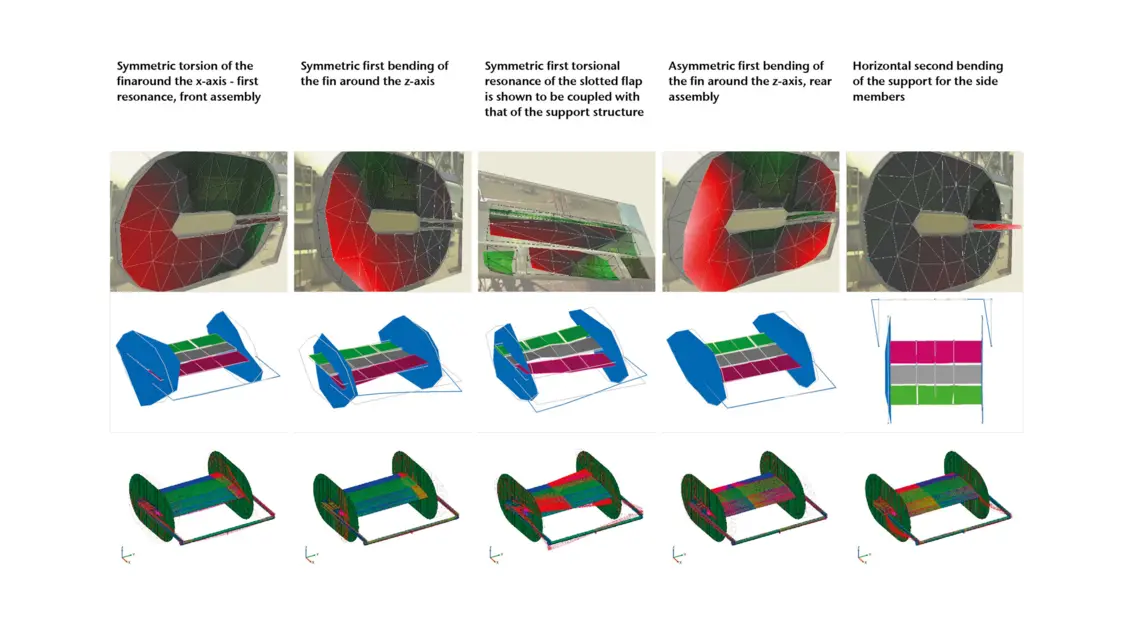
The test was designed to determine the basic dynamic characteristics of the first 20 natural modes of the prototype, which allowed the mathematical simulation to be refined to take into account complex non-linear dynamic behavior. As a result, the divergence between the computed and experimental values determined by the standard method did not exceed 6.5%.
By comparing these two test methods, important advantages of using laser Doppler vibrometers became apparent including technical and economic effectiveness. The standard phase resonance method required 13 days with 2 engineers and 2 technicians, while using Polytec’s non-contact PSV-H4 required only 5 days with 2 engineers and no technicians to achieve an acceptable quality of experimental data.
References: Kintscher M. Method for the Pre-Design of a Smart Droop Nose using a Simplex Optimization Scheme. – SAE Aerotech Congress and Exhibition, 10.-12. November 2009, Seattle, Washington, USA. Amiryants G., Malyutin V., Timokhin V. Selectively deformable structures for design of adaptive wing smart elements. 27th Congress of the International Council of the Aeronautical Sciences – ICAS2010, 19.-24. September 2010, Nice, France.